We will present here a method of calculating planing forces on a surfboard. In this playful initiation to the hydrodynamics of planing hulls and surfing, certain vulgarizations are made to maintain an intuitive vision of physical phenomena.
Here we provide a basic calculation method for surf planing forces. The proposed formulas are reduced to the minimum required to understand the flow surrounding the board and to quantify the forces produced by a board. Even simplified, hydrodynamics requires some knowledge of physics. The "Shaper Waves Dynamics" software, intended for shapers, naval architects, or simple surfers wishing to understand the planing forces in action while surfing, is available on this site.
By default, unspecified units in formulas are in international system (SI) :
Lengths, in meters
Mass and weight in kilograms Forces in Newtons (9.81 N is equivalent to the force exerted vertically by a weight of 1KG, you can simplify this relationship by admitting 1Kg ≈ 10 N)
Duration in seconds
Volume in m3
Section in m²
Speeds in m/sec
Angles in degrees
Pressures in Pascal (force of 1 newton applied to 1 m²)
The reference mark is defined at the surfer's center of support, See Surfing dynamic mark.
Just as relative flow is the current of fluid actually perceived by the board, relative profiles are the shapes actually perceived by the fluid. These profiles are sections of planks, cut along the relative direction of flow. The inspired shaper looks at the relative profiles when imagining how he wants to deviate the flow.
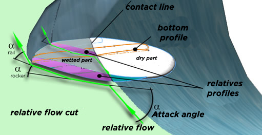
Still-point view of the board, in sections parallel to the relative flow: Relative profiles
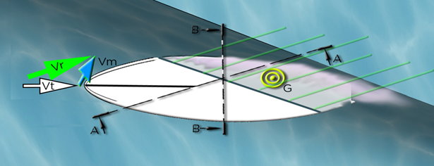
Top view of the board at the Still point: The relative flow is represented by the vector Vr, the rising flow by the vector Vm and the trajectory speed by the vector Vt
Euler's theorem tells us how a mass of fluid changes direction under the action of external forces. By analyzing the flow direction changes imposed by a board, we can know the forces exerted on a given surfboard.
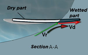
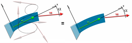
The vertical section view AA, parallel to the relative flow Vr, shows the profile and its submerged rail part (dark part), deflecting the relative flow: The relative flow is represented by the vector Vr, the bottom of the board deflects the fluid in a direction represented by the vector Vd.
PLANING ANALYSIS BY VARIATION IN QUANTITY OF MOVEMENT :
Let us take the hypothesis of a flow in 2 dimensions, on the cutting plane A-A . This representation describes the action of the bottom of the board on the vein of fluid of section S. We neglect the heavy force of the water and, in a first approach, we neglect the variations of pressure between the entry and the exit, in estimating the cross-section of deflected flow as a jet in the open air. This approach also neglects surface friction which will be detailed in the chapter dealing with the boundary layer.
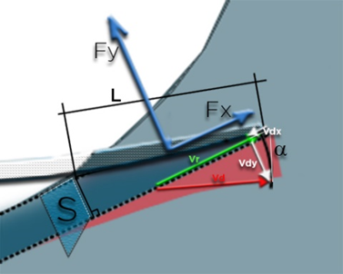
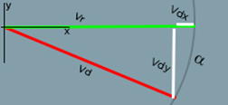
Figure 112: lift forces Fy and drag Fx, resulting from the variation in momentum of a jet of section S, (frontal surface of wetted length L), deflected along the planing angle α. The vector Vr represents the input flux, undisturbed by the bottom of the board. The vector Vd represents the deflected flux at the exit, it is considered here as parallel to the bottom of the board and of the same length as Vr. The vector Vdx is the projection of the speed variation in the x axis relative to Vr, and the vector Vdy represents the speed variation in the y axis relative to Vr.
The section S, of flow undergoing the variation of momentum, is defined by:
S(m²) = L x sin (α) x width. Equation 20
With α angle between Vr and the bottom of the board. L: wetted length, line joining the point of contact with the flow and the rearmost point where the flow separates from the board, and width: width of the board element (wet surface/wet length)
The mass flow in the control volume is defined by: :
Qm(kg/sec) =S(m²) x Vr(m/sec) x (kg/m3). Equation 21
The output velocity, Vd is identical to Vr, only the direction of the flow changes: Vdx and Vdy represent the variations between the entry and the exit of the control volume, of the velocity components in the parallel(x) and perpendicular( y) to the direction of flow, Vr (the positive downward sign of Vdy is here associated with the lift generated in response to the change in fluid motion)
Vdy= Vd x sin (α) = Vr x sin (α) Equation 22
Vdx= Vr – Vd*cos(α) = Vr- Vr*cos(α) Equation 23
The variation in momentum along the y axis represented by Vdy assumes that the direction at the exit of all the flux Vr is oriented towards a single direction, and that the speed remains constant between the entry and the exit, because the forces of pressures are neglected. This is acceptable at very low angles of incidence, or for a perfectly channeled flow in a pipe, but this becomes inadmissible at 90 degrees of incidence. Because the flow is free, under the effect of the pressure, to separate in opposite directions generating a zero Vdy sum when the incidence is at 90 degrees.
We will therefore include this phenomenon in our definition of Vdy by integrating a “simplified” pressure factor, equal to the cosine of the angle of incidence:
Equation 24: Vdy= Vr * sin (α) * cos (α)
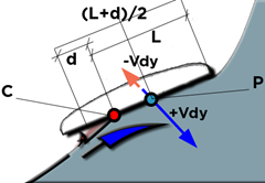
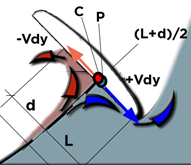
The pressure therefore generates an ejection of flux beyond the wet line L, by a distance d. If no ejection is produced (incidence 0), the distance between the theoretical contact point C, and the lift point P is 0.5 L. We estimate that the point P moves to merge with the point C when the angle of attack Reaches 90 degrees, following the approximation:
Equation 25: Distance CP= (cos (α )/2* L
Euler's theorem gives us :
Fx = Qm * Vdx Equation 26
Fy = Qm * Vdy Equation 27
The efficiency of planing is given by :
efficiency= Fy/Fx Equation 28
Let us specify that Vdx and Vdy, therefore consequently, the forces Fx and Fy, depend on the angle between the direction of entry and the direction of exit of the volume of control. We therefore see the importance of controlling the direction of the flow at the exit of the board. The role of rocker, vee, concave and rail is to steer the flow out:
intermediate directions do not impact the angle between inflow and outflow, which is the sole factor of lift.
INFLUENCE OF PLANING ANGLE OF ATTACK
Let us immediately apply the previous equations to observe only the influence of the angle of attack on planing. Let us observe the drag and lift of a 0.2 m wide board element, in contact with the water surface over a length of 0.3 m. Let us apply to this element a relative flow is 5.5 m/sec, corresponding to the progression of a wave of about 1.5m unwinding without rapid section:
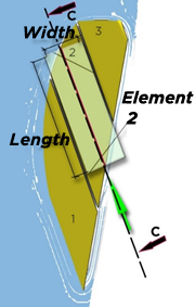
Board element 0.2m wide in planing over a length L=0.3m
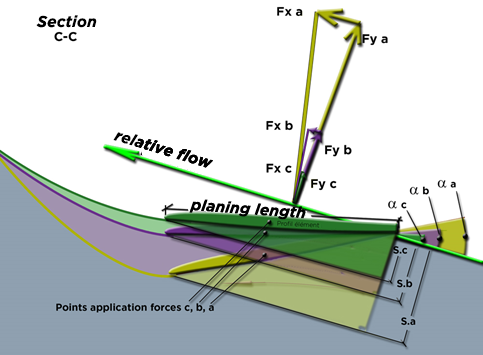
The forces Fx(abc) and Fy(abc), represented by vectors to scale in the C-C section, calculated according to the equations detailed in the previous chapter, represent respectively the drag and the lift of the board element. The drag Fx is the force of resistance to progress (parallel to the relative flow), the lift Fy is the force perpendicular to the direction of the relative flow. Sections S (abc) are determined by the angles of incidence α(abc), as follows:
S(m²) = L x sin (α) x element width. Equation 29
The flow of material deviated, formulated by Qm= S x Vr x density, increases with the section S. Note that the incidence α of the board modifies the direction of the flow, but also the quantity of flow deviated.
This graph represents the forces calculated for the element according to incidences α varying from 3° to 45°:
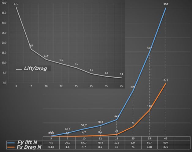
Variation of lift forces and planing drag for an elementary surface as a function of angle of attack.
We notice that at low incidence the forces are very weak, and that at high incidence they increase. By accepting the correspondence 10 N= 1 Kgf, we can notice that the lift at 25 degrees reaches approximately 32 kg for 7 kg of drag (71 newtons). The effectiveness of an airfoil results in its ability to generate lift with minimal drag. This efficiency of the profile is given on the graph by the ratio Lift/Drag = glide ratio. We observe a degradation of performance when the incidence increases.
These results seem to confirm that a board surfing flat, with a low angle of incidence, offers better hydrodynamic performance. But the proportion of planing shape resistance and friction varies with speed, and the accompanying wave resistance also provides a peak resistance depending on the froude number. See: Hydrodynamics drag surf board